|


Introduction to Landing Gear notes
The main landing gear installation is rather tricky
for most builders. There have been several tricks, by builders who have
gone on before, that make the process much less challenging. The goal
here is to consolidate everyone's tips at a location where we can gain
easy access. The tips here are taken from early newsletters, the discussion
page, and the library, so there may be some repetition across the site,
but this will allow you to see a quick summary. Before starting on the
main landing gear, it is advisable that you read everything on this page,
the library, and also view all the photos in the photo section of the
site. The thumbnails in the text below can be enlarged by clicking, then
use your browser back button to return here.
 |
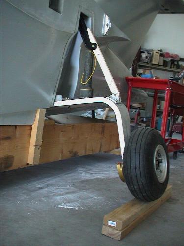
The main landing gear has to be aligned
properly to fold up into the wing, and then fold down into a position
in proper alignment to hit the runway, at 90 mph, without veering
to the side. And, it has to be properly aligned vertically so that
it will withstand the landing loads. Alignment is key. As many builders
found out early on, there is also a problem with getting the gear
attachment points low enough that the upper pivot points don't interfere
with the top of the mid deck, and high enough that the lower pivot
points don't hit the bottom skin. (Geeez, what a mouthful, you may
have to read that sentence a couple of times!)
|
|
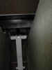
Get the lower pivot points as low as
possible, but be sure to check for adequate clearance for the aft
pipe cap that screws on the bushing inside the hull.
|
|
Lest I be crucified, let me first say
that in my career, I have written dozens of manuals and work instructions,
and I know how difficult it is to make them clear. I also know that
no matter how good they are, they are subject to interpretation by
several people, and we all see things in widely varying and different
ways. I think that, for the kit plane industry, the Seawind manuals
are pretty typical, and in places, pretty good. Having said all that,
the section on the MLG and it’s associated reinforcements inside the
hull are especially dismal and need complete revision.
 |
First, check the revisions in
the MLG section. Each page has a different revision. Also, make
sure to read the builder letter dated October 21, 1996. I used
the dimensions shown on page 4 in the manual (which includes
the suggestion from Mike Bowes to lower the gear by ½ inch to
better accommodate the upper connection point).
 |
I first located and drilled
the hole (about 1/8" lower than the manual and Mike's
letter suggest) on the aft face of the gear pocket as
shown, then, I varied the position of the hole in the
forward face to get the gear leg aligned. As the manual
suggests, I started with 1/8" holes, and then if
slight repositioning was required, I went up one or two
drill sizes and re-drilled the location, and the wooden
dowel, to accommodate the new drill size. This all seemed
to work pretty well for me.
|
|
|
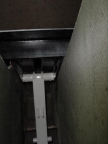
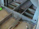
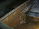
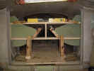
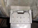
OK, the next things are the various
reinforcements in the hull. First of all, the angle supports
shown on page 18 should actually be dry fitted first, not last.
They interfere with the MLG aft floor bulkhead shown on page
16. If the manual is followed for their length, they actually
extend under the bulkhead two or three inches. After talking
with Mike Bowes, I decided to leave them as long as possible
because they are tying the hull together across the step. In
addition to bonding them as shown in the manual, I also put
a lay-up across the flange to the aft bottom, then, I cut the
bulkhead to fit over the top of these flanges and lay-ups ensuring
a good seal. (see photo below)
|
|
Next, the under-floor transverse
channel supports shown on page 13 and 15 are not properly described
in the manual. In fact, the aft channel support is shown on
page 15, but never even mentioned in the text of the manual
(let alone installed). Also, the pictures and description are
not very clear about the fact the these channels should be trimmed
at the floor beam flange, so that they are flush with the top
of the floor beams, and fit tightly against the bottom of the
aft floor. (Whatever you do, DO NOT cut the flanges on the floor
beams. Trim the flanges of the cross members) I also believe
that the flanges of the aft channel support face aft, as do
the flanges on the adjacent bulkhead sections.
|
|
Make sure that the glass cut from
templates 5.1 and 5.2 properly fits your hull before cutting
up all that 7781.
|
|
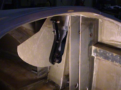
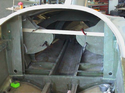
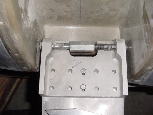
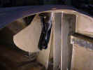
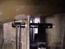
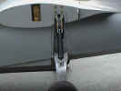
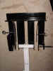
I did not bond the forward gear
enclosure panel in until AFTER the upper retraction arm pivot
point was located as seen in the photos below. When bonding
in the enclosure panels, align them by setting the exact same
dimension between the panels and the wing main spar bulkheads,
then clamp a straight edge between the two enclosures, side
to side, as shown in the photo below. Then, when bonding in
the forward enclosure panels, do the same thing, but in addition,
cut an exact 4" block, and clamp between the enclosure
panels to establish perfect spacing between the panels as shown
in the photos below.
|
|
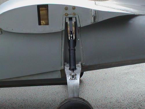
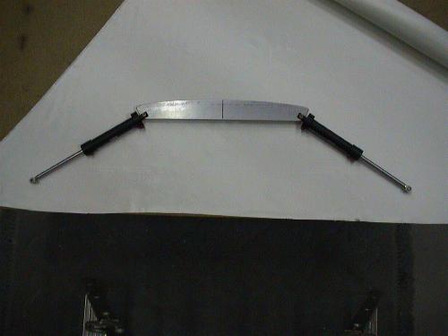
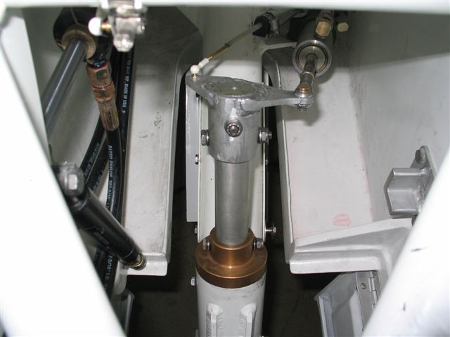
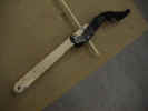
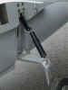
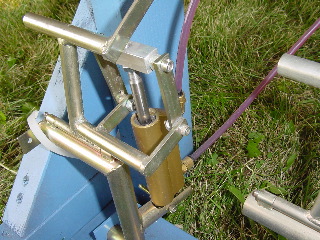
As suggested by Craig Easter and
Bob Darrah, a bar (instead of the oleo) is used to set the over-center
dimension when locating the upper pivot point. Bob nicely describes
this process in the newsletter archive (volume 2, number 2,
March 1995) so I didn't repeat it here. I used a wooden bar,
cut to the exact dimensions, and trimmed at an angle to set
3/8" over center dimension. Note, the over center dimension
is set with the oleo fully compressed length. Then, when the
oleo extends, the over center dimension increases from 3/8"
to about 3/4." This linkage must remain OVER CENTER throughout
it's travel.
|
|
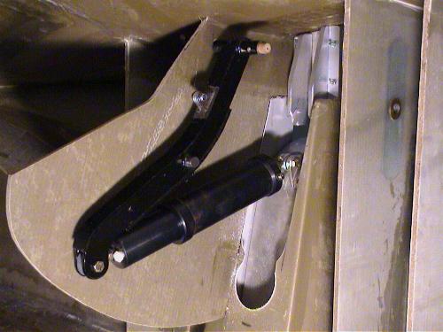
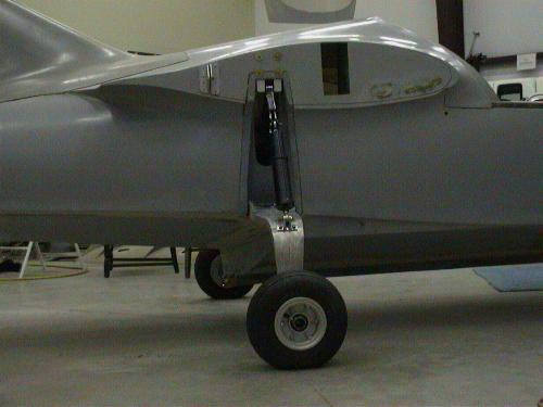
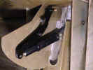
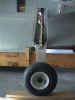
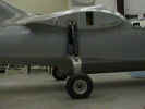
As suggested by Mike Bowes, I
set the gear legs at about 3 degrees past level when the gear
was fully down and the oleo was fully extended. I also checked
that with the oleo fully compressed, I had about 1-1/2"
clearance between the v-cuff on the keel, and the ground. You
don't want to have the belly drag if your oleos lose pressure.
|
|
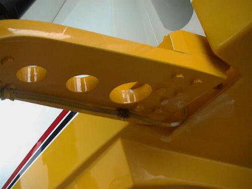
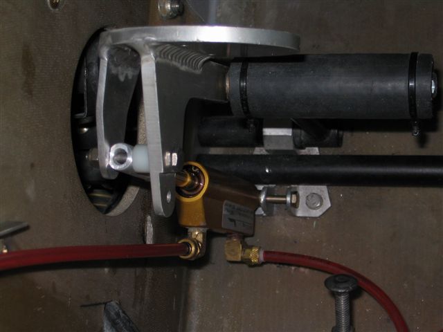
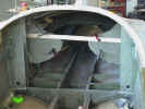
Positioning the "angle support
blocks" (I call them pillow blocks) was a real bitch! I
used the plate that Mike Bowes suggests below, but after all,
when I was trying to get the retract arm to properly engage
the notch, I had to shim the aft angle leg toward the inside
of the airplane, at the top bolt, with three standard thickness
washers. This was necessary on both sides of the hull. These
blocks must be positioned during the process of locating the
retract arm upper pivot point. I would recommend that you not
try to locate them after the arm is installed as suggested by
the manual. It is also helpful to have them in place before
the forward MLG enclosure panel goes in. This enables you to
see them, access, them, etc.
|
|

 Good luck, you're gonna need it. BAC SNA Kit# 71
|
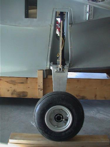
Seeing your note on the landing gear
positioning stirred memories that I had repressed about my own struggles
a few years ago. I ended up making a homemade main landing gear axle
out of two 3 in lengths of threaded rods (5/8 in I think). [Others
used 1/4" all thread and wooden or nylon bushings with 1/4"
id and 5/8" od] These were joined in the middle by a threaded
"female" union available from the hardware store. When you
turned it with a wrench or pliers, the ends of the axle moved outwards
and pressed into the sides of the wheel pocket. At first the ends
were ground to somewhat of a point to gain purchase enough in the
fiberglass. It had to be stable enough to stay put while working the
main gear legs up and down while fitting. Later, I just drilled into
the ends of this temporary axle and inserted a short length of 1/4
steel rod. All of the fitting of the gear components was done with
these and I had to move the 1/4 hole in the wheel pocket a little
on one side or the other to get everything to fit right. It was no
problem to finally ream up to the size for the bushing which was the
last thing I did. I was so pleased with this
invention, that I sent it to another builder. I hope others may find
this helpful.
|
|
Drilling the Main Landing Gear Pockets (this is also
in the library)
by Roger Isackson After
reading the instructions for locating and drilling the holes for
the bushing installation in the main landing gear pockets, it seemed
to be straight forward and logical. However, when I started to actually
drill the holes I realized it wasn't quite so simple.
The idea
to drill successively larger holes in the pocket and the temporary
bushings in the pivot bracket to adjust your hole location to the
proper place is sound. But to actually drill the holes in line with
each other is a little more difficult! I do not know of an angle
drill physically small enough but with a 7/8" capacity which
would fit in the pocket. Even then it would be hard to get perfect
alignment. I have the quick kit and the 141 & 145.55 bulkheads
are installed forward of the pocket so there isn't room to drill
from inside the hull from the front. Aft of the pocket the hull
curves in and causes interference. With the 141 & 145.55 bulkheads
installed one must drill them both to get the shaft in anyway so
it seemed logical to purchase some long drills. I located some 20"
long drills in McMaster Carr,
but the minimum set required by the construction manual ran approximately
$160.00. Also, if one reams the holes for alignment a reamer with
flutes to reach both sides of the pocket is necessary.
One note
about straight chucking reamers or hand reamers is they cut on the
nose of the tool. The flutes are only for a place for the chips
to go. So to get a perfectly aligned hole either a piloted reamer
or an expansion reamer with flutes long enough to reach both sides
of the pocket should be used. Another $60.00 to a $100.00.
It was
late, I was tired so I called it a night and slept on it. As often
happens, when I woke a simple solution popped right into my head!
I charged off to the local hardware store and purchased a 1/8"
diameter by 12" long drill bit, a 1/4" diameter by 3'
long steel rod, and a 7/8" diameter hole saw with a 1/4"
diameter pilot hole extending all the way through. 14 Bucks!
I threaded
the long drill into the holes in the pocket facing forward. I had
to enlarge the aft hole slightly to do this. Then I "align
bored" forward through bulkheads 141 & 145.55 by turning
the bit with my fingers. I increased the hole size in the bulkheads
to 1/4" then hole sawed them to 1 1/4" (I already had
that saw). Then I followed the instructions in the manual. I was
able to drill from inside the pockets up to 1/2" with my little
angle drill. That was where I was at when I was satisfied with the
hole positions.
I made
two 1/2"od X 1/4"id bushings out of delrin stock and inserted
in each side of the pocket. During a practice cut with the 7/8"
hole saw in a piece of scrap I found it to cut oversize, so I chucked
it up in a drill press and touched a grinder to the outside of the
teeth. In removing just a little of the set, I now had a hole in
which the bronze bushing would fit nicely. I ground a flat on the
1/4"rod 6 1/4" from the end for the set screw in the hole
saw, and slipped the rod in through the front of the pocket. I locked
the hole saw into position and cut the rear hole. Then I made another
bushing 7/8"od X !/4"id and pressed it into the hole I
had just cut. Now I put the "pilot rod" back into the
bushed holes with the cutter facing forward, put my drill in reverse
and cut the front hole. No chance of misalignment.
I keep
an assorted stock of delrin in the shop and seem to always be finding
a use for it. I have the luxury of owning a metal lathe, but accurate
bushings can be made with a drill press with a little care. They
can be made out of wood too, but the delrin comes accurately sized
so it is really handy. Just another way to skin the cat!
Sincerely,
Roger Isackson
Hull # 132
|
|
Post #91: This posting comes in response
to an email from a troubled builder who is second-guessing himself
as he attempts to locate the upper pivot pin bushings for the main
gear retract swing-arm. A very, very common issue. I choose to respond
here because every one of you will have this problem to some degree.
I have rigged ten Seawinds to date, and this is an ongoing problem
with all of them. Yes, follow the manual to the best of your ability
and when all else has failed resort to Mike's Tactics, as follows.
Any of the following tips will help alleviate the problems here. In
some cases ALL Of THE FOLLOWING are required to make this thing
work properly!
|
Understand the basic problem is
the lengths of the main oleo plus the swing-arm combine to create
an effective total length that threatens to push the aft upper
swing-arm bushing right through the mid-deck skin. It follows
that anything the builder does to shorten this total length
or move the swing-arm inboard (because the skin is rising toward
centerline) helps to solve the problem. These tips either shorten
the effective total length or move the upper pivot point inboard.
You builders are smart. Think about each item and it will be
self-evident how it helps you. I really don't need to explain
it.
|
|
Some or all of these tips may
be required to gain the necessary clearance. You can also remove
a little of the inside skin of the mid-deck and the foam at
the point of interference on the aft side of the pocket where
the stainless pin comes close. " Heal the core" with
2 ply of 7781 bid. Using some or all of these little tricks
has solved this problem on every Seawind. Do not modify your
swing-arms, as one builder did, with catastrophic results since
he employed ordinary mild steel in his revised creations. Believe
me, although it may seem like the answer to your woes, modifying
the swing-arm is not necessary. JMB N369JB
|
|
|
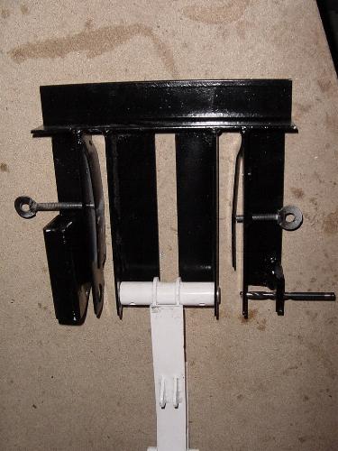
The following is from post 297, from John
Ricciotti: I would like to offer to anyone who has not yet rigged
the gear the use of some fixtures I have made.
|
|
They are as follows:
|
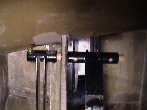
I have made an adjustable 5/8 in. shaft with
1/8 in. pins for setting the main gear pivot points (lower)
and also have made a fixture to hold the upper swing arm pivot
point in place while checking the fit. The upper fixture also
has a 1/4 in. drill guide built in to align the shaft holes
on both sides. I am still in the final stages of fitting but
they should be available soon.
|
|
|
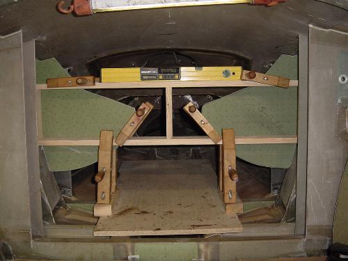
I would like to add a few observations on helpful
items that in hindsight would have made the whole gear fitting process
smoother. First, before setting the retract bulkheads, make sure
the hull is level fore and aft as well as side to side. In the manual
it doesn't point this out very clearly (the fore and aft part) but
it will make a big difference in getting the retract bulkheads plumb
to the entire gear system. Also note that the upper end of the gear
pocket has a slightly different centerline than the bottom where
the main gear bushings are set. Getting those centerlines as close
as possible from the very beginning of setting the retract enclosure
panels will be a big help. It will help to minimize the misalignment
problems that Mike Bowes has pointed out in one of the newsletters.
To help with that I made a wooden jig to hold the retract panels
in place while they were bonded. It was 2 parallel 1”x 4” (1x5 cut
down) boards set horizontally between the gear pockets with 3 vertical
boards connecting the horiz. boards together. Then it was easy to
put a level from top to bottom to make sure the whole system was
plumb. I am very close to drilling the holes and setting the bushings
in place. When I have completed that, the fixtures will become available.
I have not drilled a hole yet and hopefully the ones I drill will
be the last. I'll follow up with anything more I have learned once
the gear is all set up. Any other hints anyone has to offer would
be greatly appreciated. Thx, John
|
|
A picture of John's fixtures are shown below. Click
to enlarge.
|
Just
one comment on brakes for those of you who might not be familiar with
Matco. Every year, George Hepp, owner of Matco Manufacturing has a great
display at Oshkosh which shows how to design a more effective brake pedal
design. For those of you not fortunate enough to see his
display at Oshkosh, he has reproduced it on the MATCO
website, which is www.matcomfg.com Also you can go
directly to the write up on MAXIMIZING
THE OUTPUT OF YOU BRAKES by copying this link into your web browser
window.
http://matco.elixirlabs.com/index.php?uid=2192&page=2372
If
you have problems copying that link just go to their website and select
TECHNICAL SUPPORT
then select TROUBLESHOOTING
on that page then scroll down until you see the link MAXIMIZING
THE OUTPUT OF YOU BRAKES and click on that link.
Below
are two pictures from Matco's display at Oshkosh.
More effective setup
Less effective setup
A
recent post from Wally Weller (with some great photos included) details
items Wally has learned in trying to design a nose wheel steering system
with a linear hydraulic actuator and in correcting poor brake pedal geometry. Wally
bought his non-Quik Kit long before hydraulic nose wheel steering was
offered. His solutions to these problems follow (taken from post
1620):
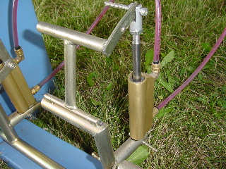
Graham (Woodd)
and I devised a linear actuator steering system with a toggle controlled
solenoid blocking valve in an interconnect between the 2 steering pressure
lines. CLOSED - hyd. steering for big turns, or hyd. lock for no shimmy.
OPEN - free swiveling for towbar handling, or rudder/brake steering straight
ahead. A manual nosewheel position indicator eliminates electrics in the
saltwater.
(We changed the
brake pedal geometry) by redrilling (which) shortened the arm that connects
the pedal and brake cylinder clevis increasing the mechanical advantage.
We moved both brake cylinders inboard 3/4 inch to clear the rudder pedal
stalks and allow full pedal application. While not eliminated, the right
pedal "lay down" geometry problem was compensated for by rigging
the right pedal about 3/4 inch aft of the left at ZERO rudder position.
The pedal stalks are now about the same angle to the deck, the brake cylinders
don't hit the deck, and pressure at the wheels has gone from a measured
250psi to 400+ psi. The brakes now hold at 2000+ rpm. Soooo, I now have
about 1 and a half inches of "builtin" right rudder travel on
T/O with pedals even, (not all bad), and some left pedal forward in cruise.
(I actually lessened it with a little padding on the left pedal) I'll
take the tradeoff, besides, my Flight Advisor, Ed Kolano, sees it as acceptable.
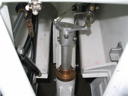
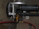
Nose
Wheel Steering w/linear actuator Brake
Pedal Geometry redesigned
(click
to enlarge pictures, browser back button to return to this page)
(Pictures
submitted by Wally Weller)
|