The following is from Scott Devlin's post 332,
November 5, 2002 (with some editing):
All
right guys I'm going to open up a big subject. We have had many posts
on landing gear. The largest issue not yet discussed here is flap mechanism,
Aft spar attach point, inboard flap hinge, wing angle of incidence.
Which comes first here the chicken or the egg? I think that the wing
angle of incidence comes first but how can you accurately set that till
you apply a template to the finished closed wings? If you place your
flap, aileron hinges permanently prior to bonding the aft wing skin
you will have less than uniform match up when you bolt them back on.
Of course you match trim the skin, but I am talking about height here.
I
want to hear about your !@$# logjams. I have had a few in this area
myself and would like some company. I also want to establish a proper
fit sequence for the future. So I will start.
The
inboard flap hinge buried in the inboard section of the flap comes in
two flavors 1 piece and 2 piece. The one piece one has a centerline
about .20 outboard of the 2 piece one. The flap needs to clear the fuselage
by .25 or it will contact the aft spar attach fitting when reflexed.
If your gap from the fuselage is too large, you are in luck, fill it
with foam, sand to shape and cover with glass. Then go to the other
side and cry like a baby. Your flap wants to sit inside the fuselage
where they touch. Now you will have to shim all the flap and aileron
hinges outboard or cut off the flap. Now you want to kill the #$%@ that
put the wing bulkheads in off center. This happened to me on a partially
completed non fast build kit that became my problem. There is a lot
more to this subject, like flap torque tube, mixer, inboard flap hinge,
aft spar bulkhead relationship, but I want to hear from Y'all, and I
gotta make some turbo heat shields. Scott
The following is from Mike Bowes' post 339, November
7, 2002 (with some editing):
Random
comments from Mike and the mechanics. Been there, done that. No need
to move wing hinges, except to shim to vertical as required. Elevator
and air rudder holes ALWAYS need to be relocated. Best way is have aft
holes filled by tig welding, machine welds flat, locate surfaces where
they need to be, center punch and re-drill 1/4" bolt holes.
Install
flap torque tube bearing blocks on outside of mid deck. Nice flat surface,
need I say more? Dimension from bearing block to rib A varies from left
to right. Therefore drive clevis must protrude from one side further
than other. So what? Do what you have to do to give sufficient clearance
to make it work. Bolt heads on the inside, nuts outside, to allow for
best straight-line alignment of stainless drive rod out to flap. A hole
in rib A at mid-travel of drive clevis allows for insertion of bolt.
See, it's easy.
Do
not alter ailerons...they are mass balanced. Instead, alter everything
around them to fit. This involves shortening one flap and lengthening
the other. So what? Do what you have to do to make it work. Nice even
1/4" straight gaps on everything that moves on this airplane. Whistle
while you work and give your sweetie a squeeze. It's a beautiful thing.
Mike N369JB
Then, from Dick Wolf's post 346, November 12,
2002 (with some editing):
Here's
a lesson I recently learned that will save you considerable time, skinned
knuckles and much cussing (did I say that?).
When
installing the aileron bell crank pivot units in the wings, temporarily
assemble the units with just enough bolts to establish the final shape
of the unit but with corner mounting bolt holes vacant so that you can
align the unit to the rib and aft wing vertical member. Drill the mounting
holes and then disassemble the unit and start installing the lower plate
and angles. Visualize how you will install and tighten each subsequent
bolt before installing the first one. Using this technique shortened
the time I took to install the second assembly by about 50% not to mention
avoiding re-scraping all my knuckles.
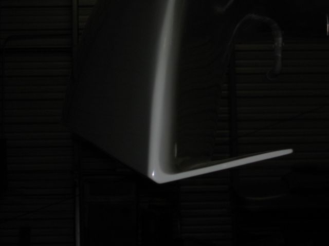
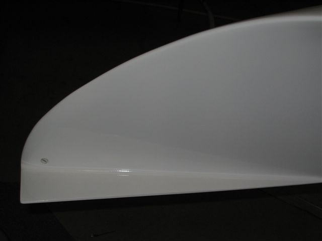
Some thought provoking hydrodynamics from Wally Weller's post 1620 :
Waterloops
-- I wish I knew the exact hydrodynamics, but suffice it to say, the
wingtip gets dragged aft smartly. I wanted more impact area (I'm an
old Lake flyer), so I added a vee splash plate, but only the inboard
half. Besides a little extra drag, water impact will now place an outward
force on the sponson. The plate being located aft of the center of pressure
of the hull, it will create a moment pushing the sponson forward, opposing
the drag. Because of the slight plate angle of attack, I think the yaw
moment in flight caused by yaw displacement will be stabilizing. I'll
probably need to keep the sponson out of the water on a step turn, but
testing will show how it balances out and I'll report it. I also feel
the absence of the outboard portion lessens the possibility of dive
in a cross controlled water contact. Anyone thinking otherwise please
say so. I'm an engineer by education, but without engineering work experience.
My ideas are just that, ideas, for my plane and your consideration.
I'm just this close to rolling down the runway, and OshKosh/Duluth are
still a possibility. But, as my good friend, Tony Jurcan says, "you
don't schedule a hobby!" Good luck. Wally
(Editor's
note: This bit of information might be a little more important
in the aftermath of John Borman's tragic water accident.)
Left
Sponson Rear View
Inboard Left Sponson View
Wally Weller's Splash Plates (photos by Wally Weller)